


Oil Well Casing
| Infobox on Oil Well Casing | |
|---|---|
| Example of Oil Well Casing | 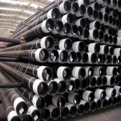 |
| Facts | |
| Origin | - |
| Stowage factor (in m3/t) | - |
| Humidity / moisture | - |
| Ventilation | - |
| Risk factors | See text |
Oil Well Casing
Contents
Description
Casing is large diameter pipe that is assembled and inserted into a recently drilled section of a borehole and typically held into place with cement.
Casing that is cemented in place aids the drilling process in several ways:
- Prevent contamination of fresh water well zones.
- Prevent unstable upper formations from caving-in and sticking the drill string or forming large caverns.
- Provides a strong upper foundation to use high-density drilling fluid to continue drilling deeper.
- Isolates different zones, that may have different pressures or fluids - known as zonal isolation, in the drilled formations from one another.
- Seals off high pressure zones from the surface, avoiding potential for a blowout
- Prevents fluid loss into or contamination of production zones.
- Provides a smooth internal bore for installing production equipment.
A slightly different metal string, called production tubing, is often used without cement in the smallest casing of a well completion to contain production fluids and convey them to the surface from an underground reservoir.
Design
In the planning stages of a well a drilling engineer, usually with input from geologists and others, will pick strategic depths at which the hole will need to be cased in order for drilling to reach the desired total depth. This decision is often based on subsurface data such as formation pressures, strengths, and makeup, and is balanced against the cost objectives and desired drilling strategy.
With the casing set depths determined, hole sizes and casing sizes must follow. The hole drilled for each casing string must be large enough to easily fit the casing inside it, allowing room for cement between the outside of the casing and the hole. Also, the inside diameter of the first casing string must be large enough to fit the second bit that will continue drilling. Thus, each casing string will have a subsequently smaller diameter.
The inside diameter of the final casing string (or penultimate one in some instances of a liner completion) must accommodate the production tubing and associated hardware such as packers, gas lift mandrels and subsurface safety valves.
Casing design for each size is done by calculating the worst conditions that may be faced during drilling and production. Mechanical properties of designed pipes such as collapse resistance, burst pressure, and axial tensile strength must be sufficient for the worst conditions.
Casing strings are supported by casing hangers that are set in the wellhead, which later will be topped with the Christmas tree. The wellhead usually is installed on top of the first casing string after it has been cemented in place.
Intervals
Typically, a well contains multiple intervals of casing successively placed within the previous casing run. The following casing intervals are typically used in an oil or gas well:
- Conductor casing
- Surface casing
- Intermediate casing (optional)
- Production casing
- Production liner
The conductor casing serves as a support during drilling operations, to flowback returns during drilling and cementing of the surface casing, and to prevent collapse of the loose soil near the surface. It can normally vary from sizes such as 18" to 30".
The purpose of surface casing is to isolate freshwater zones so that they are not contaminated during drilling and completion. Surface casing is the most strictly regulated due to these environmental concerns, which can include regulation of casing depth and cement quality. A typical size of surface casing is 13⅜ inches.
Intermediate casing may be necessary on longer drilling intervals where necessary drilling mud weight to prevent blowouts may cause a hydrostatic pressure that can fracture shallower or deeper formations. Casing placement is selected so that the hydrostatic pressure of the drilling fluid remains between In order to reduce cost, a liner may be used which extends just above the shoe (bottom) of the previous casing interval and hung off downhole rather than at the surface. It may typically be 7", although many liners match the diameter of the production tubing.
Few wells actually produce through casing, since producing fluids can corrode steel or form deposits such as asphaltenes or paraffin waxes and the larger diameter can make flow unstable. Production tubing is therefore installed inside the last casing string and the tubing annulus is usually sealed at the bottom of the tubing by a packer. Tubing is easier to remove for maintenance, replacement, or for various types of workover operations. It is significantly lighter than casing and does not require a drilling rig to run in and out of hole; smaller "service rigs" are used for this purpose.
Cementing
Cementing is performed by circulating a cement slurry through the inside of the casing and out into the annulus through the casing shoe at the bottom of the casing string. In order to precisely place the cement slurry at a required interval on the outside of the casing, a plug is pumped with a displacement fluid behind the cement slurry column, which "bumps" in the casing shoe and prevents further flow of fluid through the shoe. This bump can be seen at surface as a pressure spike at the cement pump. To prevent the cement from flowing back into the inside of the casing, a float collar above the casing shoe acts as a check valve and prevents fluid from flowing up through the shoe from the annulus.
Casing and tubing strings are the main parts of the well construction. All wells drilled for the purpose of oil or gas production (or injecting materials into underground formations) must be cased with material with sufficient strength and functionality.
Casing
Casing is the major structural component of a well. Casing is needed to:
- Maintain borehole stability
- Prevent contamination of water sands
- Isolate water from producing formations
- Control well pressures during drilling, production, and workover operations
Casing provides locations for the installation of:
- Blowout preventers
- Wellhead equipment
- Production packers
- Production tubing
The cost of casing is a major part of the overall well cost, so selection of casing size, grade, connectors, and setting depth is a primary engineering and economic consideration.
Casing strings
There are six basic types of casing strings:
- Conductor Casing
- Surface Casing
- Intermediate Casing
- Production Casing
- Liner
Conductor casing
Conductor casing is the first string set below the structural casing (i.e., drive pipe or marine conductor run to protect loose near-surface formations and to enable circulation of drilling fluid). The conductor isolates unconsolidated formations and water sands and protects against shallow gas. This is usually the string onto which the casing head is installed. A diverter or a blowout prevention (BOP) stack may be installed onto this string. When cemented, this string is typically cemented to the surface or to the mudline in offshore wells.
Surface casing
Surface casing is set to provide blowout protection, isolate water sands, and prevent lost circulation. It also often provides adequate shoe strength to drill into high-pressure transition zones. In deviated wells, the surface casing may cover the build section to prevent keyseating of the formation during deeper drilling. This string is typically cemented to the surface or to the mudline in offshore wells.
Intermediate casing
Intermediate casing is set to isolate:
- Unstable hole sections
- Lost-circulation zones
- Low-pressure zones
- Production zones
It is often set in the transition zone from normal to abnormal pressure. The casing cement top must isolate any hydrocarbon zones. Some wells require multiple intermediate strings. Some intermediate strings may also be production strings if a liner is run beneath them.
Production casing
Production casing is used to isolate production zones and contain formation pressures in the event of a tubing leak. It may also be exposed to:
- Injection pressures from fracture jobs
- Downcasing, gas lift
- The injection of inhibitor oil
A good primary cement job is very critical for this string.
Liner
Liner is a casing string that does not extend back to the wellhead, but is hung from another casing string. Liners are used instead of full casing strings to:
- Reduce cost
- Improve hydraulic performance when drilling deeper
- Allow the use of larger tubing above the liner top
- Not represent a tension limitation for a rig
Liners can be either an intermediate or a production string. Liners are typically cemented over their entire length.
Tieback string
Tieback string is a casing string that provides additional pressure integrity from the liner top to the wellhead. An intermediate tieback is used to isolate a casing string that cannot withstand possible pressure loads if drilling is continued (usually because of excessive wear or higher than anticipated pressures). Similarly, a production tieback isolates an intermediate string from production loads. Tiebacks can be uncemented or partially cemented. An example of a typical casing program that illustrates each of the specified casing string types is shown in Fig. 1.
